


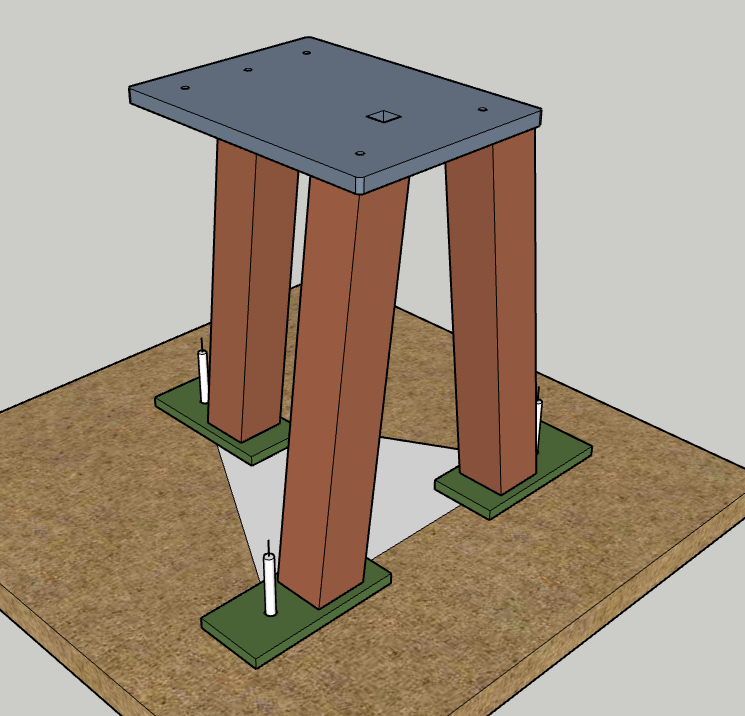
The striking anvil, pictured here, is designed to be used in conjunction with a striker. This particular style was taught to me by Brian Brazeal several years ago, and has only seen a few modifications from that time.
The all steel, tripod design, lends itself to a stable platform on most any suitable surface. The face of the “standard” anvil comes in at 24” and there is a reason for this. When stacking a billet onto a bottom tool, and then stacking a top tool atop the billet… the height can grow quite significantly. We measured nearly 10” of additional height when upsetting a 4.5” long hammer billet! This allows our striker to come down onto the tooling with as much force as possible, without requiring them to stand on boxes… However, some of our shorter friends still might need that box… :)
I use this same basic design for all of my “regular” anvil stands.
If you CLEAN the concrete and apply a little hot glue to each foot; the stand will not walk around on you should you opt to anchor it to concrete. We did this with a striking anvil that received HEAVY usage over a weekend and it did not move, and easily pried off the floor without damaging it.
Striking Anvil Cut List
(3) 3” Square Tubes, 7° cut for a 14° combined angle. Legs are cut at 21.5”
4” x 9” x 5/8”; these will become the feet
12” x 16” x 3/4”; this will be your base plate / safety plate
11” x 5” x [2-3]” plate - this will become your anvil
3/8” holes 2” offset from each edge, in the corners. A fifth 3/8” hole is centered on the plate,, 1.5” from the edge. These are used for adding sand to the legs, as well as mount points for a tool rack. We do not weld the tool racks into place so they can be removed for transport and/or specific forging operations. A future article will go over creating these racks.
Drill, plasma, EDM, laser,, water jet, torch… Whatever you need to do, center a 1.25” hole (square or round) 5.5” off the back edge of the plate. Once your anvil is aligned, this hole should allow a 1” bar to pass through without obstruction.

Legs & Feet
You will want to mark your legs at approximately 21.5” and set your saw to cut 7° on each side. When stood up, the combined angle is 14°. We’ve found this to be a great angle for stability and strength. This length will get your anvil height to right at 24” if using all the same dimensions listed above. You might need to play around with this length if you change things up though.
I drill a 5/8” hole in each foot 2” in from the top edge, centered. This is used to anchor the stand either to concrete with concrete anchors, or stakes (I use 10” stakes) on dirt.

Welding
Prep all of your material prior to welding. Adding a heavy chamfer on all parts to be welded allows for a much heavier bead. First, you will want to position and weld the back legs to the base plate. I position this square to the piece, about 1/4” off of each edge. Tack weld one leg into place, ensuring it’s square. Once tacked, you can then position the second leg and use a piece of flat bar clamped between the two legs to ensure that they are in the same plane. Tack this leg into place. Make sure you placed the back legs nearest the oversized hole in the base plate. This is where the majority of your heavy forging will take place; so this is where you want the most support.
Next position the front leg. I center this on the base plate and move it about 1.5” off the edge. This provides a little more clearance for the tools hanging in the rack, else there can be a 3” square tube in the way, right in the middle. This gets a little annoying and I wish I had figured this out before making 5 of these things…

Now flip the stand over and position the feet under the legs. I like to see at least 3” of foot sticking out from the leg, and 2” under the stand. Unless you are planning to do the equal lateral hole pattern, you can pretty much position these however you like.
For the equal lateral pattern. You should have a fabrication table with the pattern laid out and 1/2” holes drilled. Take some 1/2” pins and pin the feet to the table. Position the stand on the feet and line them up as equally and squarely as you can. This will ensure, no matter how off your positioning is… The hole patterns will always be the same.
For the welds around the legs and feet, you want to make them as water tight as you can. If you’re welds are anything like mine… it won’t be water tight. I’ve found that a little silicone around the weld seams can really help here. Once you add sand and oil to the legs, they can leak if you don’t have waterproof weld seams, and that adds up to a bit of a mess.